
A major North American pipeline operator was having difficulty inspecting deep well booster pumps tasked with moving crude oil. The pumps are designed to be removed from the 18’ deep steel wells for repair and maintenance, but the wells themselves are installed in concrete casings. Inspecting the wells requires the operator to take them out of service for extended periods of time to remove and inspect.
The pipeline operator approached Diakont to develop a robotic solution capable of inspecting the deep wells without removing them from the concrete. The robotic solution uses electromagnetic acoustic transducers (EMAT) and laser profilometry to provide comprehensive data for both the vertical well barrel and the horizontal flat cap at the bottom of the well.
Challenge
- Difficulty inspecting a deep well booster pump(that moves crude oil)from aNorth American Pipeline operator.
Solution
- Diakont’s standard robotic in-line inspection (ILI) crawler was identified to handle the integrity assessment of this section.
Results
- It was discovered that one suction barrel had a gouge in the steel bar that bisected the well cap in addition to a deformation above the well cap The second suction barrel had no significant issues or metal loss, allowing the pipeline operators to take the necessary precautions needed for the first
Previously Uninspected Assets
A major North American pipeline operator used vertical can-type pumps to move crude oil efficiently around storage facilities. The system comprises an 18’ steel suction barrel and a vertical turbine pump. The suction barrel is buried in concrete with an opening at the grade level. The turbine pump is installed in the suction barrel, then connected to the crude pipeline via an inlet pipe and suction discharge head. See Figure 1.
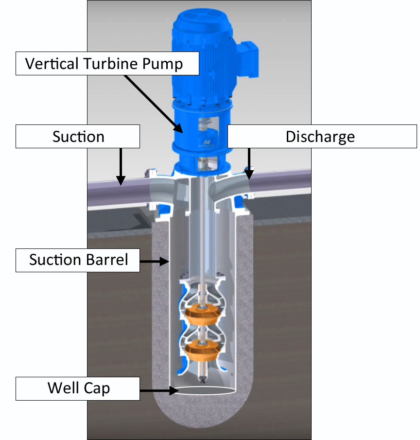
Figure 1. Deep well booster pump diagram
The vertical turbine pump is installed via bolts; it can be removed for integrity assessments fairly simply. However, the buried suction barrel requires complete excavation to inspect using traditional methods. This inspection process was expensive, time-consuming, and risked damaging the barrel. For these reasons, the pipeline operator contacted Diakont to develop a new robotic solution to inspect the barrels in situ. For the initial inspection project, the pipeline operator identified two suction barrels 12’ deep with diameters between 20” and 40”.
Inspection Solution
The walls of the suction barrels have the same characteristics as a vertical unpiggable pipe section. Diakont’s standard robotic in-line inspection (ILI) crawler was identified to handle the integrity assessment of this section.
The bi-directional crawler employs three tank-like tracks; two at the bottom of the tool for primary propulsion, and a third upper track that extends to stabilize the tool in difficult geometries such as bends, inclined, and vertical segments. See Figure 2.
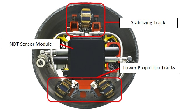
Figure 2. Unpiggable ILI crawler track configuration
Diakont’s robotic crawler uses an integrated sensor suite to assess pipe wall integrity:
- Ultrasonic testing (UT) electromagnetic acoustic transducers (EMAT) measure pipeline wall thickness.
- A laser profilometer creates detailed mapping of the pipeline’s inner surface as well as detects and measures internal surface irregularities such as pitting.
- High-definition cameras allow technicians to gather photographs and video of the pipeline interior.
Unlike conventional UT instruments, the EMAT instrument does not require liquid couplant between the transducers and the pipe body to transmit ultrasonic signals, making it ideal for inspections where liquid within the lines is impractical or unacceptable. All sensor data feeds back to the inspection technicians in real time via an umbilical cable and pipeline operators are given same-day assessment results.
New Tooling Development
The well cap at the bottom of the suction barrel could not be inspected with Diakont’s standard ILI tooling, which rotates the EMAT transducers circumferentially to scan pipe walls as shown in Figure 2. The NDT module design had to be modified so that the sensors could make contact with the bottom plate.
Diakont’s engineering group accomplished this by mounting the sensors on a linear actuator on the front of the module to move the sensors across the surface area of the well cap (see figure 3). This NDT module modification accommodated both EMAT and laser profilometry sensor suites.
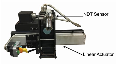
Figure 3. NDT sensor mounted on linear actuator for well cap inspections
Tool Testing
Diakont built two in-house mockups of the deep well suction barrels to test and verify the sensor modifications for the different can diameters (see Figure 4). The mockup barrels were also used to train inspection technicians on new crane and inspection tool operating procedures before deploying to the customer site.
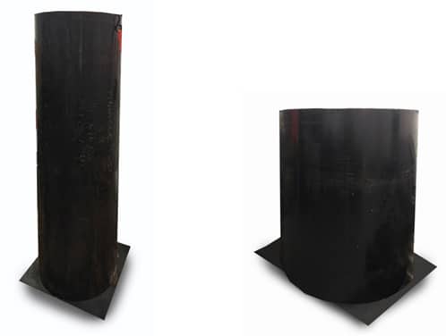
Figure 4. Suction barrel mockups (20” at left, 36”-40” at right)
Inspection Procedure
The pipeline operator identified two deep well suction barrels for the initial inspection project. The first suction barrel was 20” in diameter and 12’ deep. The second suction barrel was 36” in diameter at the opening, with a reducer located 10.75’ down widening to 40” diameter for the last 6’ to the well cap.
Before the inspection team deployed to the facility, the pipeline operator shut down the pipe system and removed the vertical turbine pumps. Each well was cleaned using a high-pressure water jet system to expose the well barrel and cap surfaces for inspection signal integrity; the laser profilometer sensor cannot scan through any sludge or debris, while cleaning is recommended to mitigate signal noise during EMAT inspection.
When working near the wells, technicians secured themselves with a safety harness and tether to prevent injuries from falling down the wells. A lifting crane was installed above each well to help orient the robotic crawlers before beginning each tool run (see figure 5). Inspection technicians lowered the crawlers into the wells and extended the tracks into the well walls, holding the crawlers rigidly in place.
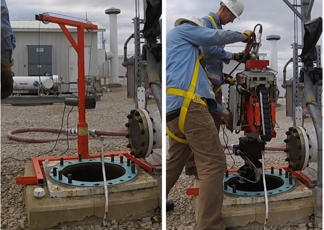
Figure 5. Robot positioning crane
Inspection technicians scanned the well caps first to avoid dislodging any remnant debris from the well barrel onto the bottom and reducing data quality. Technicians scanned the well cap in circular patterns beginning at the center of the cap, then stepping out the linear actuator to scan the next ring until 100% of the cap surface was inspected – figure 6 shows the well cap next to the concentric rings of the laser profilometer scans.
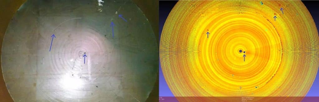
Figure 6. Well cap compared to the laser profilometry scans
Inspection Results
The 20” diameter suction barrel inspection revealed a 2” gouge in the steel bar that bisected the well cap; Figure 7 shows a photograph of the gouge, while Figure 8 shows the Diakont laser profilometry scan of the gouge. In the same suction barrel, deformation was discovered at distance of 4.4’ above the well cap (see Figure 9). On the second suction barrel, the robotic crawler successfully navigated the reducer to inspect the barrel wall and the well cap. No significant issues or metal loss were detected while inspecting the section suction barrel; remaining wall thickness measurements were all above the thresholds of 0.1604” for the well barrel and 1.887” for the well cap.
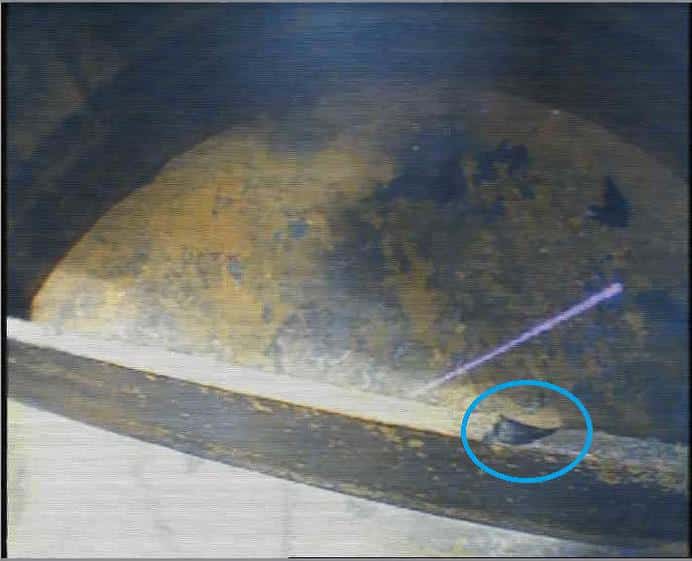
Figure 7. Gouge on steel bar bisecting the well cap
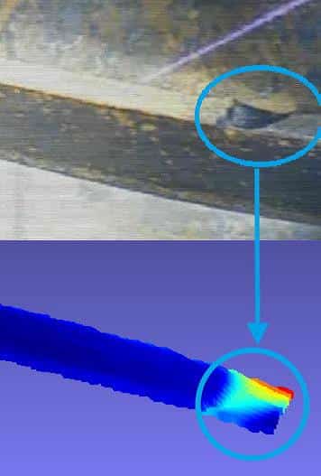
Figure 7. Gouge on steel bar bisecting the well cap
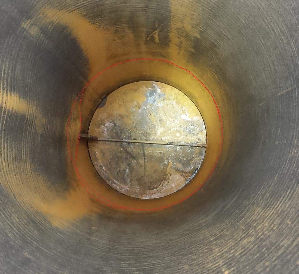
Figure 9. Deformation at 4.4’ above the well cap


