
Challenge
- Inspect an aboveground petroleum storage tank built to API 650.
- Environment: submerged, petroleum, flammable vapor, magnetometer and GPS-denied, zero visibility.
- Inspection criteria: API 653.
- Acceptance criteria: determine the remaining service life of the tank’s floor plates prior to repair or replacement.
Solution
- Utilize Diakont’s Stingray System inspection tool to inspect the tank’s floor, which was 80’ in diameter and 40’ in height, with a fixed cone roof supported by seven internal columns.
Results
- The scanned coverage exceeded what was planned. 96% of the total floor area was scannable, leaving the areas under the base plates from the seven support columns and floor-mounted drain lines unscannable due to the inability to access.
Inspection Requirement
In this case study, a Salt Lake City, UT refinery operator had an aboveground petroleum storage tank as part of one of their process units that was due for its required inspection based upon the facility’s Risk-Based Inspection (RBI) program. Due to the process flow within the unit, taking this particular tank out of service for a several-week turnaround would have had substantial negative impact on production. Considering that the tank was expected to be in sufficiently-good condition that would allow extension of the operating cycle under the parameters of the RBI program, the facility operator made the decision to evaluate conducting the required in-service API 653 inspection while the tank remained filled and in-operation.
The operator first had their embedded NDE contractor perform external manual assessments of the integrity of the shell, roof, and external appurtenances. Once these were determined to be in good condition that would support extension of the operating cycle, the facility then proceeded to plan the inspection of the floor plates.
Asset Details
This tank was constructed from steel to API 650 requirements. It was 80’ in diameter and 40’ in height, with a fixed cone roof supported by 7 internal columns. The floor plates were of typical construction with lap welded plates. This tank did not have an annular ring. The internal floor and lower portion of the shell was coated with a thick epoxy-based liner.
The tank contained unfinished diesel, with frequent flow and level changes. There was a thin (<1”) coating of sludge spread across the tank floor. Visibility within the tank was near-zero.
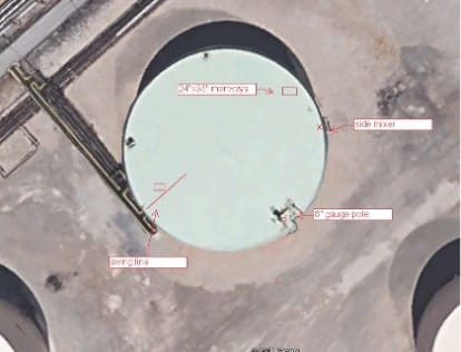 Tank overview
Inspection Technology Selection
A purpose-designed tank floor inspection crawler method was selected by the facility operator for conducting this project. Since the tank floor plates were in contact with the soil and supporting the liquid, access to the plates was only possible from inside the tank. Alternative indicative methods such as acoustic emission did not provide sufficient NDE resolution to satisfy the requirements of the RBI program administrator. The environment in the tank required safe, effective operation while submerged in petroleum and solid sludge, with access through an area of flammable vapor, and operation with no guidance from visual, GPS, or magnetometer sensors.
The facility operator considered multiple robotic NDE service providers for this project. The chosen technology was selected based upon:
- Meeting legal requirement of having NEC Class 1 Division 1 certification by a regulated body, for electrical equipment or umbilicals operating in the vapor space in the tank above the liquid level
- Having validated NDE technologies that met the API 653 requirements through a proven statistical analysis and real-world validations, with same or better effectiveness and coverage than would be achieved in a traditional out-of-service inspection
- Being operated by a robotic NDE service provider that was well-trusted, with certified quality system and ASNT-compliant operator qualifications
The facility operator selected Diakont to perform this inspection project, using their Stingray robotic tank floor inspection system. The system consisted of a 4-wheeled robotic crawler tool that traverses the tank floor, deployed into the tank from a hoist structure temporarily mounted to a roof manway hatch. The robotic crawler is equipped with 2 different NDE systems – both Magnetic Flux Leakage (MFL) and a 96-element array of immersion UT probes. The “critical zone” area adjacent to the floor-to-shell weld is interrogated to within the requirements of the standard. Travel is encoded, and orientation is maintained using fiber-optic gyroscopes. The tool is connected via an umbilical to a control station in a modular container away from the tank. Control software performs Simultaneous Localization and Mapping (SLAM), such that a tank floor map is built as the floor is scanned, plate-by-plate. The system operates in a semi-autonomous mode, with a Level II NDE Technician monitoring tool and NDE operation. Multiple video cameras on the tool record roof and coating condition, and are used for obstacle avoidance in clear (e.g. gasoline, alcohol, jet fuel) liquids. Obstacle avoidance in tanks without visibility (e.g. diesel, crude oil) is performed using 3D imaging sonars on the front and rear of the robotic crawler tool. Concurrently with the exam, internal out-of-plane settlement is measured, as required by the standard.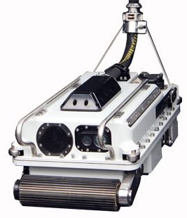
Diakont Stingray System Inspection Tool used in this project
Inspection Operation
To complete the inspection, the equipment was mobilized to site and staged. Electrical elements were bonded and grounded. Checkout and “cal-in” (verification) of the NDE systems were performed. The tank fill valve was temporarily blocked and locked/tagged-out (leaving suction in operation), and the permit for the inspection was issued.
The in-tank equipment and launcher were then raised to the tank roof via crane, along with liquid containment berms for use on retrieval. The manway hatch was removed, and the launcher was affixed to the manway flange.
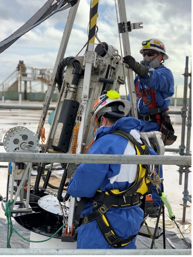 Technicians preparing for tool launch from roof (comparable photo from different tank)
The tool was then lowered into the tank, and while doing so a general visual exam was performed of the viewable area of the roof underside, to look for evidence of corrosion and condition of coating. The tool was then lowered to the tank floor. The temporary manway hatch seal was closed, the technicians secured the roof, and returned to the control station. At this point the tank fill valve was unblocked, so that the tank could resume full operation.
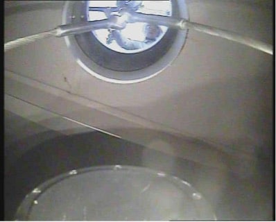 View of the roof underside
The inspection was conducted over the next days, on a plate-by-plate basis. The MFL and UT were used in parallel. The MFL was the detection NDE technology, providing a very robust NDE technique that tolerates topside corrosion and sludge which would cause signal loss with other methods such as PAUT. The UT array provided high-resolution absolute measurement and profiling of detected anomalies. Over 90 million UT A-scans were recorded.
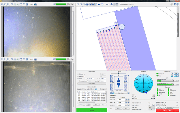 Operator screen showing autonomous planned motion path and heavy sludge on camera views
Results
The inspection was completed as-planned. The scanned coverage exceeded plan, with 96% of the total floor area scanned; just the area of the base plates under the 7 support columns and the floor-mounted drain line were not scanned due to not being accessible.
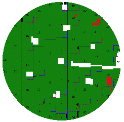 MFL encoded C-Scan display of mapped tank floor (Green area is above reporting threshold thickness, red is anomalous, and white is unscanned due to obstacles)
The initial results from the inspection were delivered to the facility operator in a preliminary report shortly after the inspection. A final report with complete analyzed results and assessment were delivered 30 days following demobilization from the site.
The facility’s API 653 inspector used the results of this inspection, plus the other external inspection data, to complete a comprehensive report on the tank that was required to meet corporate and state regulatory requirements. The tank floor and the balance of the tank were in quite good condition, such that the RBI program allowed extending the operational period of the tank for 15 additional years. Between the savings from avoiding the out-of-service turnaround, and avoiding the loss of productivity – the facility operator estimates that their same-year cost savings was approximately $1.1M.


