
Challenge
- Pipeline inspection in vapor or partially-submerged, flammable vapor
- Inspection criteria: various (10CF192, 10CFR195, ASME FFS-1, NRC license renewal obligations, other ASME code, etc.)
- Acceptance criteria: identification measurement, and characterization of anomalies
Solution
- Utilize Diakont’s 8-14” robotic tooling to inspect the pipeline’s interior.
Results
- A detailed report of the inspection project, pipeline feature list, anomaly tally, snips of NDE data, graphs, photos, and videos, were provided to the customer with potential anomalies and measurements.
- This report is also used to perform engineering analysis’s regarding the condition of the lines and objects of the inspection project.
Inspection Requirement
For many years, inspection of piping and pipelines was limited either to using “free-swimming” flow-driven inspection tools (“pigs”), or performing inspections manually using hand tools such as UT probes.
The free-swimming pigs, typically with UT, MFL, or geometry sensors, are quite useful in that they can cover a long distance, and in some cases operate while the piping is in-operation with its normal transport contents (whether liquid or vapor). However for shorter piping lengths such as inside facilities, extensive pumps and piping modifications may be required. On longer lengths special launchers and receivers (“traps”) are generally installed, either temporarily or permanently. In either scenario, the piping or pipeline geometry and features must be able to accommodate the tool without it getting stuck. It is generally not possible to stop or reverse the tool partway through the inspection.
It is also possible to inspect piping from the outside using a hand scanner or “bracelet” probe, however this method is obviously only reasonable for short distances of piping, and it must be accessible by personnel from the outside.
The integrity of piping assets must be assured, for safety and environmental compliance, and also to meet regulatory and code requirements. Piping is generally operated at a pressure above atmosphere; for example, large-diameter natural gas transmission pipelines may operate above 1000 psi. Liquid pipelines must be able to withstand substantial pressure transients from multi-phase scenarios. Many pipelines carry hazardous or flammable contents that can cause explosion or ignition, or substantial environmental damages. A piping failure inside a facility can cause damage to personnel and other assets within the facility.
These inspections may be performed for a variety of reasons, including the following:
- Meeting regulatory or code requirements
- Performing secondary, higher-resolution inspection following a free-swimming ILI run
- Performing inspection following initial installation, particularly following HDD
- To assess condition of line in preparation for a change in service, or potential abandonment
- Performing special inspection following a failure, to determine the extent of condition
- To assess condition and also special geometric parameters of the piping in preparation for remediation (pipe-in-pipe, SIPP or composite repair, etc.)
Asset Details
Pressure piping and pipelines are built in wide variety of configurations.
Pipelines are generally located below-grade, although may sometimes be above grade and even over aerial crossings. They typically run horizontal to grade, although this may still result in substantial vertical angle changes. Bends and tee-connections may be welded forged elbows, may be field-fabricated, or may just be pipe routed in a curve over a certain long radius. Valves are typically full-diameter ball-style, although this may not always be the case. Reducers may or not be concentric. And tee-connections may or may not be barred.
Piping in facilities such as refineries, compressor stations, and power plants may include all of the above; and typically have more complex geometry than longer-distance pipelines.
The most common material for piping is carbon steel of various grades, although piping can also be stainless steel, cast iron, concrete, or concrete composite. Piping may be internally lined with mortar, or epoxy or other materials. The piping exterior may be coated with materials such as coal tar, wrapped, or may be encased in concrete. Piping may be in the soil, or inside buildings.
Pipe contents in operation may be petroleum liquids, natural gas (methane), crude oil, water, or any variety of other liquids, gasses, and even slurries. The interior surface may contain foreign material, and there may also be the presence of corrosion scale.
Inspection Technology
Diakont began the development of tooling and started providing robotic inspection services of piping in 2004, originally in the complex geometry and single-valve-isolated piping of gas compressor stations. Diakont now has a family of modular tools for varying conditions and pipe diameters, deployed on a global basis.
These tools are all robotic and mostly tethered in nature, for use when the piping is depressurized. They are semi-autonomous, with operators controlling the tool from a base station some distance away. The tethered tools can be deployed from an entry point to a distance of up to approximately ½ of a mile. The robotic tools accommodate bends, tees, vertical sections, and reducer transitions. They may be certified for use in hazardous environments with flammable vapor, and partially full of liquid. They deploy NDE technology that is suitable for the objectives of the inspection, and the pipe material and condition. These NDE payloads may include remote visual, EMAT-UT, PEC, ACFM, or laser scanning.
A separate control system provides power and control, and collects NDE data. Localization feedback comes from encoders and accelerometers. NDE scanning is automated.
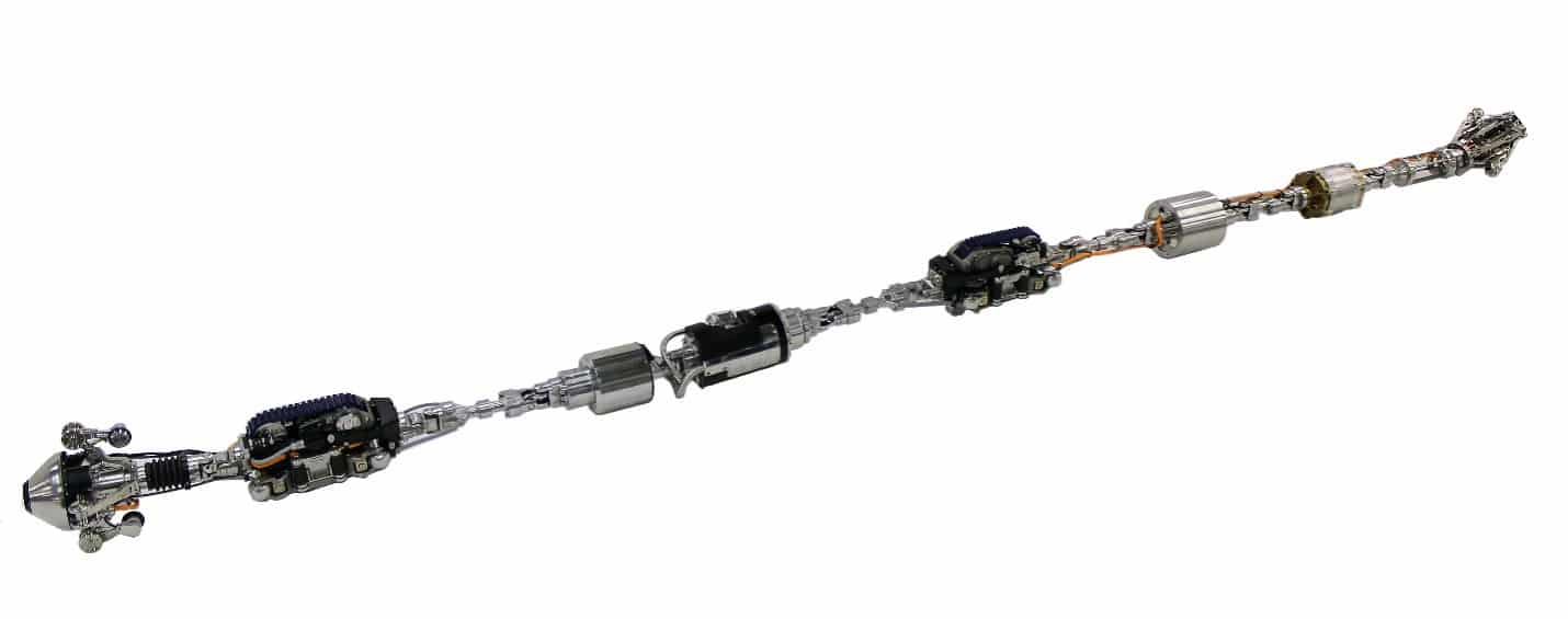 Diakont 8-14” Robotic Tool
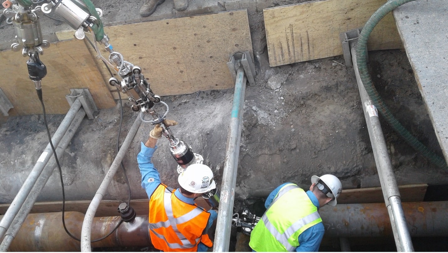
Robotic Tool Launch into Natural Gas Transmission Pipeline
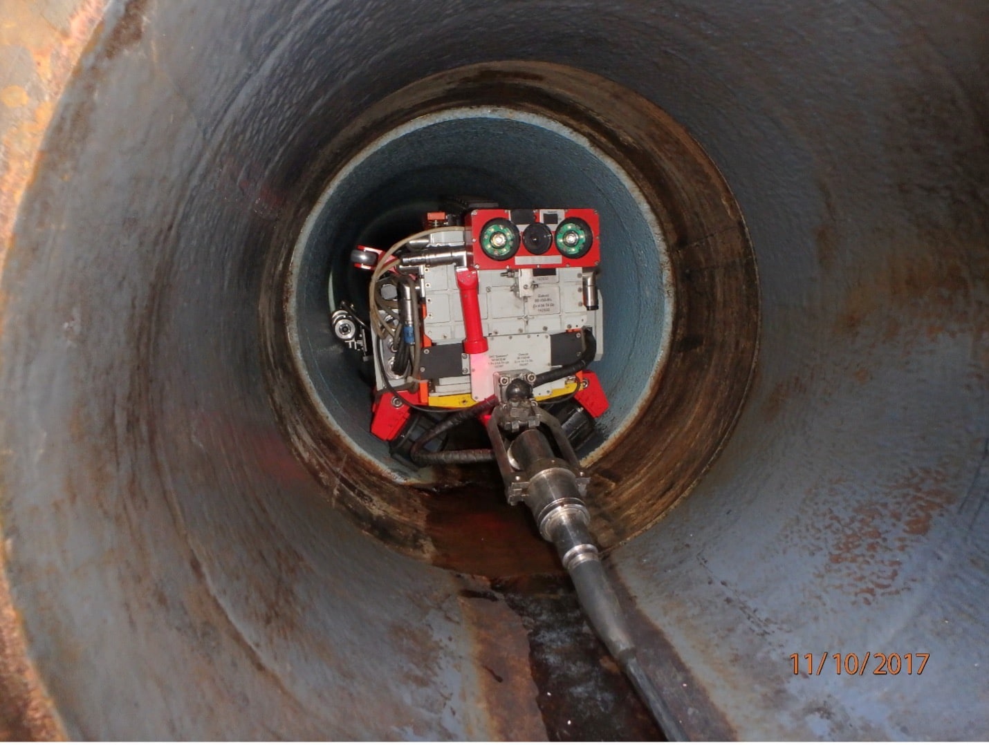
Robotic Tool Entering a 22” Pipe-in-Pipe Section to Perform an EMAT-UT Examination
Inspection Operation
Inspection is typically performed by launching the robotic tool into a pipe via a removed valve, blind flange, or open face. Prior to launch, NDE sensors are verified and/or calibrated. The tool then traverses to the inspection area, which may comprise the entire distance from a launch point, or may be a shorter segment some distance away. Pipe features are logged as they are identified. The robotic tool is retrieved in the similar matter to how it was launched, followed by re-verifying NDE sensor performance.
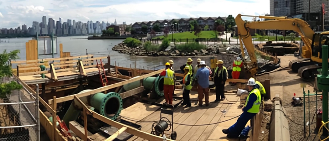
Launch of a Robotic Tool on a Natural Gas Pipeline River Crossing
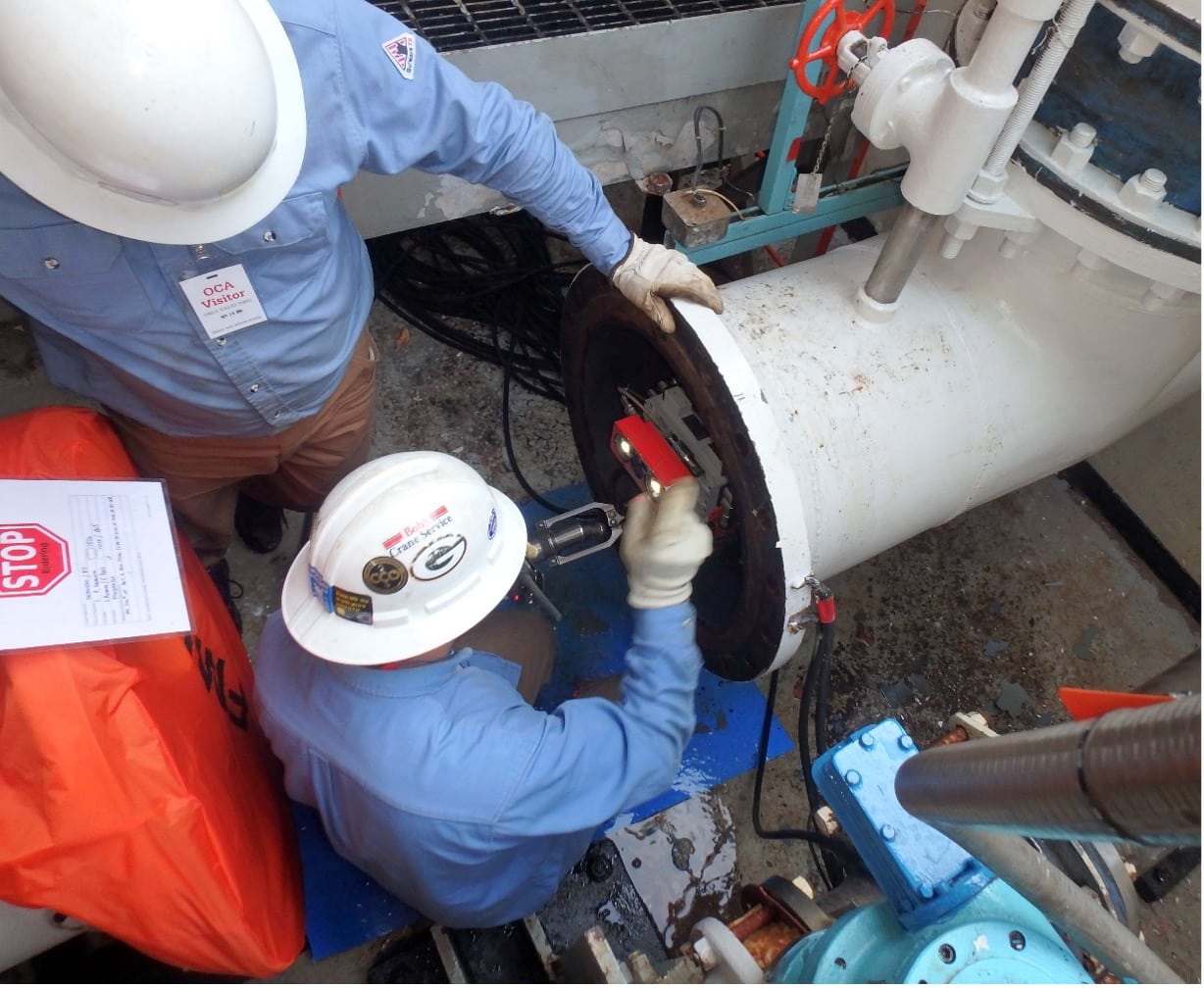
Launch of a Robotic Tool into Coolant Water Piping at a Nuclear Power Plant
Results
NDE data is analyzed and reported to the asset operator or other contracting entity following the project. This includes a description of the inspection project, and may include a pipeline feature list, anomaly tally, snips of NDE data, graphs, photos, and video.
This report is often then used to performing engineering analysis of the condition of the line, in accordance with the objectives of the inspection project.


